Software projects often need command line tools that automate specific tasks, such as code generation, evaluations, packaging, etc. All too frequently, these tools are developed ad hoc and unstructured, implemented, quickly finished, and then forgotten. Unfortunately, this makes them difficult to understand and maintenance-intensive later on. Good software documentation can help circumvent this problem. This article proposes a supplementary measure: a simple software architecture for command line tools, designed to facilitate understanding and further development of the same.
Software Architecture
Automate the boring stuff - Al Sweigart
The following image depicts the proposed software architecture of a command line tool.
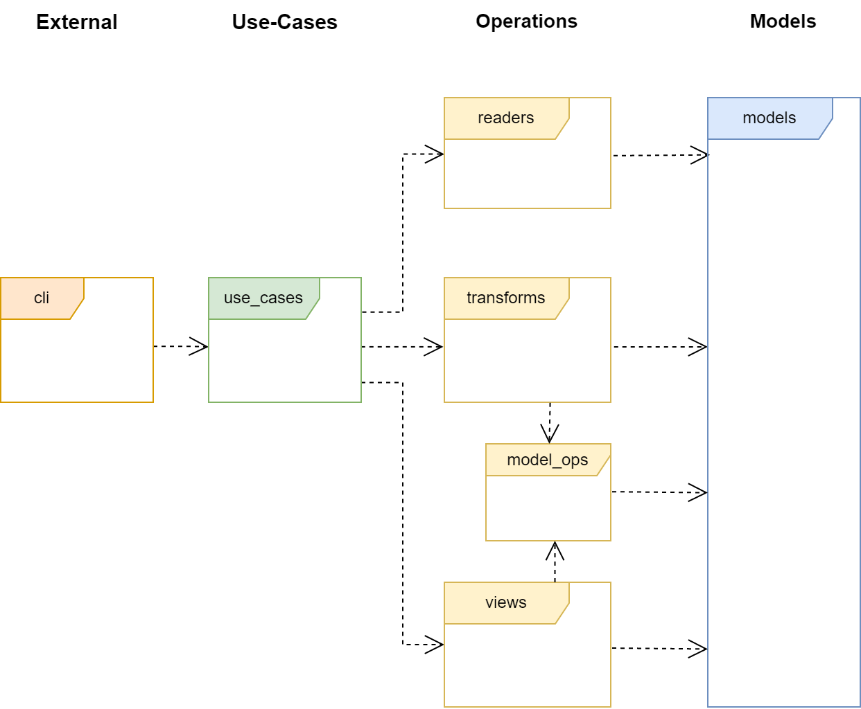
The image shows a UML package diagram. However, don’t let this designation confuse you - in the present case, only namespaces and their relationships to one another are depicted. A namespace is nothing more than a container for code (e.g., classes).
Note: In Python, I define a namespace simply as a module including submodules.
The arrows in the diagram symbolize dependencies, which are best explained by the sentence “A uses B.” With regard to the diagram, this means, for example, “cli uses use_cases.” Note that the relationships are directed: use_cases is forbidden from “using” cli.
For further information about the different types of dependencies in UML, I refer you to my own article on this topic. You can find it here!
The namespaces in the image are organized in layers. This is indicated on the one hand by the color of the namespace, and on the other hand by the name of the layer above the namespaces it contains. As an example: The Operations layer contains all yellow-marked namespaces.
Layers
The architecture of a command line tool is divided into four layers: External, Use-Cases, Operations, and Models. The most important rule is that a layer may only have dependencies on the next lower layer. Based on painful experience, I recommend strictly adhering to this rule to avoid a disorganized and incomprehensible architecture.
Each layer has specific tasks and functions, which are explained below.
External: This layer connects the program with the external world. Here, the command line options are processed. Ideally, a library should be used here that handles this task. Note: With Python, I prefer Click for this task.
Use-Cases: In this layer lie the use cases of the tool. A use case describes a single task to be executed, such as “Convert file from format A to format B.” It should be named and documented accordingly.
Operations: In this layer lie the classes necessary for carrying out the task. In the present case, these are classes for reading the data model (read), classes for transforming one data model into another (transform), and finally classes for displaying a data model (view).
Models: Finally, there is the Models layer. This contains all data models. According to Wikipedia, we define a data model here as a “model of the data to be processed within an application domain and their relationships to one another.” This layer should contain as little logic as possible.
Note: With Python, I recommend using dataclasses and/or named tuples to model the data.
Detailed Explanation
The details of our architecture are best explained using an example. Let’s assume that a user uses our command line tool as follows:
my_tool file1.xyz file2.xyz
After this invocation, the following happens: The code in the cli namespace (external layer) evaluates the command line arguments and then executes a use case from the use_cases namespace. I see the use case as an independent task of the command line tool.
For example, let’s assume that my_tool has the task of converting all characters in a file to uppercase. In this case, the corresponding use case might look like this:
uc_convert_all_chars_to_uppercase(…)
Note: Please note that all code examples contained here do not correspond to any real, existing programming language. They serve only illustrative purposes.
Within the use case, the actual task is processed. Since a command line tool typically does not require any further input during execution, you can always structure it according to the IPO model. This means that you divide the task into an input, a processing, and an output step. The use case executes these steps always in this order, without exceptions!
Caution: It is tempting to read files throughout the entire program runtime. My advice: Avoid that! You have enough memory. Load everything you need into memory and process it there. This makes the process much clearer.
The IPO model is mapped in our architecture as follows:
Input - corresponds to the read namespace
Processing - corresponds to the transform namespace
Output - corresponds to the view namespace
Thus, our architecture provides each of these steps with its own namespace and thereby a space for its implementation. The steps taken together form the Operations layer.
In the read namespace, files are read and converted into a data model, for example reading file1.xyz. The resulting data model is returned to the use case.
With this model as an argument, the use case executes one or more operations in the transform namespace to bring the data into the desired format. In the example, we would convert the character strings present in memory to uppercase and then return them to the use case.
Finally, the transformed model is displayed through operations in the view namespace. In the example, this means we save the results in file2.xyz.
Taken together, the example use case could now look as follows:
uc_convert_all_chars_to_uppercase(…) {
  // Input
  model = read.read_file(...)

  // Processing
  t_model = transform.transform_model(model)

  // Output
  view.write_tmodel(t_model)
}
The namespace model_ops, as depicted in the UML diagram, occupies a special position. It contains general model logic that can and should also be used by the views. Often, these are iterators that represent a model in a particular way. It would be paradoxical to implement this logic separately in each namespace, which is why the model_ops namespace exists.
A word of warning: The namespace models is not intended to contain business logic that goes beyond the scope of a model. The namespace model_ops can also be used for this purpose. Where exactly the line is drawn depends on your personal judgment.
Why So Concrete? That’s Hard to Test!
If you take a closer look at the previous example and the architecture, you will see that functions from one namespace are called directly by functions in another namespace. For example, a use case uses functions from the transform namespace. Of course, it is also possible to implement everything as objects and to implement these objects against interfaces. These interfaces are then used as a communication channel between the layers. This principle, known as Dependency Inversion, is naturally not excluded. Particularly with statically typed programming languages (e.g., C++), I would choose this path for complex tasks. It enables a more testable application, but in my opinion makes it less clear. For simple projects, I therefore advise against it.
For dynamically typed programming languages (e.g., Python), there is also the option to “patch” calls in code to be tested. An example of this is Monkey Patching, well-known in Python. It enables the modification of code at runtime. This allows the insertion of mocks, as with the Dependency Inversion principle, but without the additional step of inserting interfaces. This often represents a good alternative if a testable tool is required.
Project Structure
Finally, the question remains of how the architecture can be implemented in a project. Currently, I use the approach of creating a separate directory for each namespace. I prefer a flat mapping of the architecture onto the directories, meaning all namespaces are located directly under the main directory.
However, this does not mean that the layered architecture should be disregarded. With these aspects in mind, I propose the following project structure:
.\external
.\model_ops
.\models
.\readers
.\transforms
.\use_cases
.\views
{: .notice–info} In Python, the modules containing the respective objects are found under these directories.
For very simple projects, the proposed structure can also be implemented in a single file. It is up to you to design the structure so that it always remains useful and practical.
Summary
The article presents a simple, layered architecture for the development of command line tools. The architecture consists of four main components: External, Use-Cases, Operations, and Models. The External layer serves as a bridge to the outside world, the Use-Cases layer defines the tasks of the tool, the Operations layer provides functions for task execution, and the Models layer houses the data models. This structure facilitates the understanding and development of such tools.